Product Grid
Level-2 Joint Atmosphere Product (ATM L2) parameters are produced at a spatial resolution of either a 5x5 or 10x10 kilometer (at nadir) pixel array. Each ATM L2 product file covers a five-minute time interval (based on the start time of each MODIS Level-1B granule). This means that for 5km resolution parameters the output grid is 270 pixels in width by 406 pixels in length for approximately nine consecutive granules. Every (approximately) tenth granule has an output grid size of 270 by 408 pixels. For 10km resolution parameters, the output grid is 135 pixels in width by 203 pixels in length for approximately nine consecutive granules. Every (approximately) tenth granule has an output grid size of 135 by 204 pixels. The granule size pattern is sporadic due to scanner inconsistency. Finally, the spatial resolution of individual parameters is detailed on the Format & Content page.
The image below depicts MODIS Level-2 granule coverage during a single simulated orbit. It should be noted that a granule of Level-2 MODIS data is equal to a single Level-2 MODIS product HDF file.
![]()
![]()
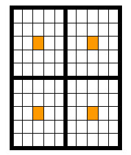
10-km Geolocation (Copied from the Aerosol (04_L2) Product)
The geolocation in the standard 04_L2 MODIS Aerosol product is at 10-km resolution. This geolocation is generated from 10x10 1-km L1B input and is computed by averaging the 4 central (5,5), (5,6), (6,5), (6.,6) 1-km L1B input pixels in each 10x10 km area. This 10-km Geolocation is copied directly from the Aerosol (04_L2) Product file input into the Joint L2 (ATML2) Product file output.
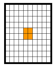
5-km Geolocation (Copied from the Cloud (06_L2) Product)
The geolocation in the 06_L2 MODIS product is at 5-km resolution. This geolocation is generated from 5x5 1-km L1B input and is copied from center (3,3) 1-km L1B input pixel in each 5x5-km area. This 5-km Geolocation is copied directly from the Cloud (06_L2) Product file input into the Joint L2 (ATML2) Product file output.
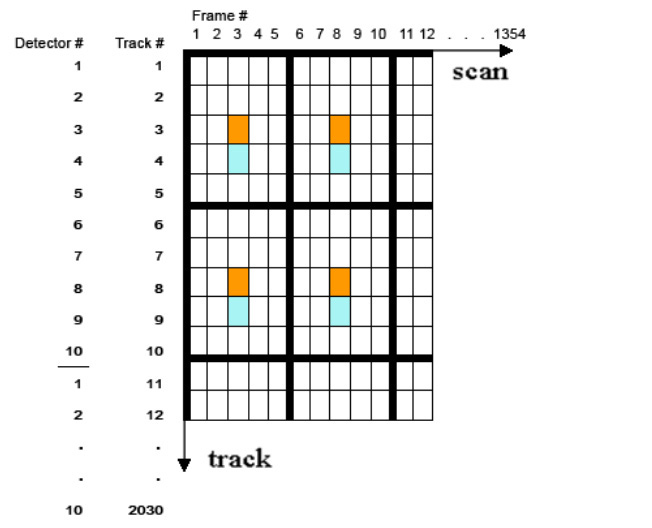
Sampling modification (starting in C005) to avoid dead detectors when sampling 1km products to 5km
A software modification was introduced in Collection 5 (introduced in calendar year 2008) and continued forward into future Collections, which offset slightly the L2 data point sampled. This patch only impacts data that are derived from sampled L2 data and includes: Water Vapor (05_L2), Cirrus Detection and Cloud Optical Property (06_L2) parameters, all of which are computed and stored at 1 km resolution in the L2 files but are sampled at 5 km resolution for computation of L3 gridded statistics. In these cases, the geolocation matches the 1-km area corresponding to the orange square in the figure below. This corresponds to the 1-km pixel located in column 3, row 3. However, the actual L2 data are sampled from the blue square (1 km pixel located in column 3, row 4). In other words, L2 data from MODIS detectors 4 and 9 are sampled (instead of detectors 3 and 8) in the 10-detector set. This patch was necessary because in some critical MODIS spectral bands on the Aqua platform, detectors 3 and 8 both died (that is, always contained missing data); so a shift to adjacent detectors was necessary to prevent many sub-sampled products from being completely missing (fill values) in L3.